The ports of the ESP8266 can yield a maximal current of 12 mA.
This is perfect to control other ports and drive LED, but way too low to drive even the smallest motors and other real world objects.
Moreover, the maximum voltage of 3.3 volt will be insufficient in most situation to drive these objects.
In order to handle bigger currents and higher voltages there is the motor shield.
Although the name suggest that this shield must be coupled to motors, it is in fact very suited to drive any electrical object. Typical examples are electromagnets, lamps and buzzers.
This shield can handle 15 volt and 1.2 ampere (3.2 ampere peak) for each of the two motor outputs. For even higher currents and voltages we need more powerful motor shields, a relay.
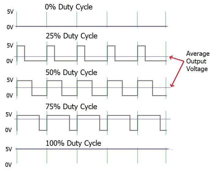
Motor shields use PWM, see image below, signals to control the power given to the motor, and hence the speed, while preserving maximal torque.
The wave form is exactly identical to the PWM signals used to control to position of a servo motor.
Here the motor does not contain a feedback mechanism for the position.
The duty cycle of the PWM signal just controls the speed.
By switching the wires or the direction from the motor shield the motor can turn in the reverse direction.
Some motor shields have additional options, like short circuiting the connections of the motor to stop it as fast as possible.

There are two version of the motor shield used in the lab. Their use is very similar, but there are differences in the hardware as well as in the software. We will discus both versions.
Both versions of the motor shield are however contected to same only require different software.
The shield is connected by stacking it on top of the Wemos D1 Mini, or next to it on a triple base. This will provide a communication channel and a ground. However power is not provided this way. The shield must be powered by an external power source for most applications.
Note
In for the first assignment you can use the
5Voutput of the Wemos D1 Mini to power the shield. This is only possible if the motors are not too power hungry. For later application you will need to consinder power usage.
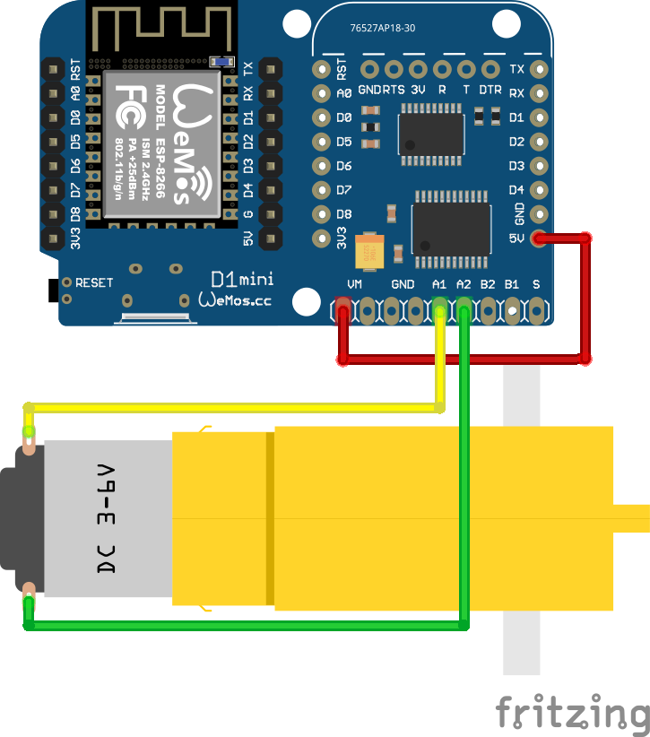
The motor shield has 6 IO pins, 4 of which are used to control the motors the two A pins and the two B pins. It also has a VM and GND pin, for voltage and ground respectively. The VM pin is used to power the motors, and the GND pin is used to ground the motors. For our toy motors, we can use the 5V output of the Wemos D1 Mini to power the motors by connecting a jumper cable from the bottom right 5V pin to the VM pin on the motor shield. For the ground we do not need to do the same, because it is already connected through the stacking of the shields.
To connect the motor we connect both leads to A1 and A2 or B1 and B2. The order does not matter, but the motor will turn in the opposite direction if the leads are switched. See the image below for the connections.

Wemos Motor shield version 1.0.0
This motor shield uses WEMOS_Motor_Shield_Arduino_Library and comes with some examples.
A basic example to speed up the motor connected to output A in small steps is:
#include "WEMOS_Motor.h"

#define I2C_ADDRESS 0x30
#define PWM_FREQUENCY 1000

Motor MA(I2C_ADDRESS, _MOTOR_A, PWM_FREQUENCY); // define Motor A

void setup() { }

void loop() {
	for (int duty = 40; duty <= 100; duty += 1) {
		MA.setmotor( _CW, duty); // _CW: Clock Wise; _CCW: Counter Clock Wise
		delay(200);
	}
	MA.setmotor(_STANDBY);
	delay(500);
}
Weird behavior V 1.0
Many 1.0 versions of this shield contain a severe software error. After sending an
I2Ccommand to this shield the shield will block to proper operation of theI2Cbus unless it receives a new message within a few seconds.There are at least two solutions for this problem. First, we can reprogram the STM32F030 microprocessor controlling this shield as outlined at here. Second, we can prevent that this bug causes harm by sending the current state to shield, even if the state is not changed. When we have a
loopthat never takes more then a few seconds it is sufficient to write the required state of the shield in every loop. The most effective way to prevent those problems is using version 2 of this shield.
Wemos Motor shield version 2.0.0
This moter shield uses LOLIN_I2C_MOTOR_Library and comes with some examples.
Note
This libary has a notable issue when used in combination with the
Wemos OLED button shield. They both use the samenamespace
A basic example to speed up the motor connected to output A in small steps is:
#include <Wire.h>
#include <LOLIN_I2C_MOTOR.h>

#define PWM_FREQUENCY 1000

LOLIN_I2C_MOTOR motor(DEFAULT_I2C_MOTOR_ADDRESS);
	//I2C address 0x30 SEE NOTE BELOW

void setup() {
	//wait until motor shield ready.
	while (motor.PRODUCT_ID != PRODUCT_ID_I2C_MOTOR) {
		motor.getInfo();
	}
}

void loop() {
	motor.changeFreq(MOTOR_CH_BOTH, PWM_FREQUENCY);
	motor.changeStatus(MOTOR_CH_A, MOTOR_STATUS_CCW);
	for (int duty = 40; duty <= 100; duty += 1) {
		motor.changeDuty(MOTOR_CH_A, duty);
		delay(200);
	}
	motor.changeStatus(MOTOR_CH_A, MOTOR_STATUS_STANDBY);
	delay(500);
}
Shield not found / wrong address
The
I2Caddress of this shield can be changed by a program included in the library. This is very convenient to solve address clashes, for instance when you want to use more than one motor shield in your project. The motor shield stores this address internally. As a consequence, theI2Caddress of this motor shield might be different from the default address. In some cases it appears necessary to try the address update a couple of times before it is successful. To find the correct address you can use theI2Cscanner in the Arduino IDE see I2C scanner.
Troubleshooting
The motor does not turn
Check whether the motor it self works by connecting it directly to the power source. You can do this by touch one lead to the ground and the other to 3.3V or 5V. If the motor does not turn, it is broken.
The motor shield does not respond
Check whether the motor shield is connected to the
I2Cbus. You can do this by running theI2Cscanner in the Arduino IDE see I2C scanner. Try a different motor shield to narrow down the problem. If the motor shield is still not found check the wiring and the power supply of the motor shield.