Information
This section will contain information such as, how to solder, how to use the 3d printer, etc.
Arduino IDE
Arduino is a c-like IDE which handles code for micro control units (MCU’s), this is because the software stack is different in an MCU than in a laptop. Which means that the arduino IDE has stripped some functionality from c++ and has implemented some more functionality necessary for running your hardware specific code.
To learn more about the basics of programming with Arduino, see here.
Soldering
Soldering is the most stable way to connect wires, components and even to create artwork! We use soldering in this course to connect components or wires to eachother in a way such that they will have good ‘contact’.
How does a soldering iron work and how to use
A soldering iron is a hot rod of metal which can heat up a metal with a low melting point, like Pb-Sn (solder or a lead and tin alloy). With the soldering iron you heat up both the wire and the contact, then you place the solder on the contact and the wire and let it flow onto both. Here you don’t directly touch the soldering iron to the solder, but you touch the solder to the contact and the wire, else the solder will not flow onto the contact and the wire but stick to the iron. Most solder contains flux, which is a chemical which helps the solder flow onto the contact and the wire. This flux will burn off when you heat up the solder, if you heat up the solder for to long the flux will burn off and the solder will flow nicely anymore. This is why you should only heat up the solder for a short amount of time.
How to check a connection
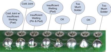
The check if a solder connection is proper you need to check the following things:
- Is the solder connection shiny? If it is, then it is a good connection.
- Is the solder connection dull? If it is, then it is a bad connection.
- Is the solder connection ‘flat’ or drawn out? If it is, then it is a good connection.
- Is the solder connection ‘blobby’? If it is, then it is a bad connection.
The main principal is that the solder should have flown and solidified after flowing with good surface tension on both objects. If this is not the case then probably one of the surfaces was not hot enough.

3D Printing
3D printing is a useful tool to custom print parts and create structures for your project to be based around. With only four 3D printers available at the New Devices Lab shared among over 100 students (50 groups), your should ensure that your entire project does not depend solely on 3D printing. If you require any 3D printed parts for your project, you have to design these yourself. For this you need to create a 3D model in CAD (Computer Assisted Design) Software. For a more in depth guide on creating 3D models, see here.
After you have created your 3D model, you need to prepare it to be 3D printed, which you can learn more about here.
Debugging Components
There are two sides to debugging embedded devices, either on the hardware or the software side. Hardware issues are usually a lot easier to solve than software issues. Below, we will discuss some common issues to check for in both hardware and software debugging.
Debugging Hardware
To properly debug hardware, the first step would be to ensure that your electrical diagram is correct. Check that all the connections have been made in the correct way and that there are no loose contacts. If there are no issues with the electrical diagram, there are three things that may have happened:
- The hardware component is broken
- There is a conflict with another connected component
- The issue is software-based
Debugging Software
Debug messages can sometimes be very confusing. As an example, we look at the following error message: error: line 9, bit.h, BIT(0) does not exist. When you see this you could conclude that the function you are trying to use does not exist. However, it does! The problem with this message is that it does not take into account that the wrong board was selected. The board ‘Wemos D1 R1 & mini’ should have been selected, but the real selection was ‘Wemos D1 R2’.
So, to quickly identify any software issues the first step is to ensure the following:
- Our setup is correct
- All libraries are installed correctly
- The right board is selected
Only after you confirm these were done correctly we start looking at what might be wrong in the code, it will probably save some headaches.
Next, due to the differences in the software stack in laptops and MCU’s, don’t expect the exact same function which works on your normal IDE to work the same way in the arduino IDE. For more information, see here.
Technical Issues
There is a list of commonly known issues, for example: “Ubuntu 22.04 cannot find the Wemos board” where the solution is as easy as running 4 commands in the command line to fix. However, debugging these is a nightmare if you don’t have any experience in this. Which is why we have a list below to see if your issue is a common one, if your issue is not in the list please contact an SA or teacher.